Tuesday, 27 May 2008

Vlan mikrotik

VLAN

Document revision:1.3 (October 11, 2007, 17:38 GMT)
Applies to: V3.0

General Information

Summary

VLAN is an implementation of the 802.1Q VLAN protocol for MikroTik RouterOS. It allows you to have multiple Virtual LANs on a single ethernet or wireless interface, giving the ability to segregate LANs efficiently. It supports up to 4095 VLAN interfaces, each with a unique VLAN ID, per ethernet device. VLAN priorites may also be used and manipulated. Many routers, including Cisco and Linux based, and many Layer 2 switches use VLAN to enable multiple independent, isolated networks to exist on the same physical network.

A VLAN is a logical grouping that allows end users to communicate as if they were physically connected to a single isolated LAN, independent of the physical configuration of the network. VLAN support adds a new dimension of security and cost savings permitting the sharing of a physical network infrastructure and interfaces/ports while logically maintaining separation among unrelated users.

Specifications

Packages required: system
License required: Level1 (limited to 1 vlan) , Level3
Submenu level: /interface vlan
Standards and Technologies: VLAN (IEEE 802.1Q)
Hardware usage: Not significant

Description

VLANs are simply a way of grouping a set of switch ports together so that they form a logical network, separate from any other such group. It may also be understood as breaking one physical switch into several independent parts. Within a single switch this is straightforward local configuration. When the VLAN extends over more than one switch, the inter-switch links have to become trunks, on which packets are tagged to indicate which VLAN they belong to.

You can use MikroTik RouterOS (as well as Cisco IOS, Linux and other router systems) to mark these packets as well as to accept and route marked ones.

As VLAN works on OSI Layer 2, it can be used just as any other network interface without any restrictions. VLAN successfully passes through regular Ethernet bridges.

You can also transport VLANs over wireless links and put multiple VLAN interfaces on a single wireless interface. Note that as VLAN is not a full tunnel protocol (i.e., it does not have additional fields to transport MAC addresses of sender and recipient), the same limitation applies to bridging over VLAN as to bridging plain wireless interfaces. In other words, while wireless clients may participate in VLANs put on wireless interfaces, it is not possible to have VLAN put on a wireless interface in station mode bridged with any other interface.

Currently supported Ethernet interfaces

This is a list of network interfaces on which VLAN was tested and worked. Note that there might be many other interfaces that support VLAN, but they just were not checked. Most modern Ethernet interfaces support VLAN.

  • Realtek 8139
  • Intel PRO/100
  • Intel PRO1000 server adapter
  • National Semiconductor DP83816 based cards (RouterBOARD200 onboard Ethernet, RouterBOARD 24 card)
  • National Semiconductor DP83815 (Soekris onboard Ethernet)
  • VIA VT6105M based cards (RouterBOARD 44 card)
  • VIA VT6105
  • VIA VT6102 (VIA EPIA onboard Ethernet)

This is a list of network interfaces on which VLAN was tested and worked, but WITHOUT LARGE PACKET (>1496 bytes) SUPPORT:

  • 3Com 3c59x PCI
  • DEC 21140 (tulip)

Additional Resources

VLAN Setup

Submenu level: /interface vlan

Property Description

arp (disabled | enabled | proxy-arp | reply-only; default: enabled) - Address Resolution Protocol mode
disabled - the interface will not use ARP protocol
enabled - the interface will fully use ARP protocol
proxy-arp - the interface will be an ARP proxy
reply-only - the interface will only reply to the requests for to its own IP addresses, but neighbor MAC addresses will be gathered from /ip arp statically set table only
interface (name) - physical interface to the network where the VLAN is putmtu (integer; default: 1500) - Maximum Transmission Unitname (name) - interface name for referencevlan-id (integer; default: 1) - Virtual LAN identifier or tag that is used to distinguish VLANs. Must be equal for all computers that belong to the same VLAN.

Notes

MTU should be set to 1500 bytes as on Ethernet interfaces. But this may not work with some Ethernet cards that do not support receiving/transmitting of full size Ethernet packets with VLAN header added (1500 bytes data + 4 bytes VLAN header + 14 bytes Ethernet header). In this situation MTU 1496 can be used, but note that this will cause packet fragmentation if larger packets have to be sent over interface. At the same time remember that MTU 1496 may cause problems if path MTU discovery is not working properly between source and destination.

Example

To add and enable a VLAN interface named test with vlan-id=1 on interface ether1:

[admin@MikroTik] interface vlan> add name=test vlan-id=1 interface=ether1
[admin@MikroTik] interface vlan> print
Flags: X - disabled, R - running
# NAME MTU ARP VLAN-ID INTERFACE
0 X test 1500 enabled 1 ether1
[admin@MikroTik] interface vlan> enable 0
[admin@MikroTik] interface vlan> print
Flags: X - disabled, R - running
# NAME MTU ARP VLAN-ID INTERFACE
0 R test 1500 enabled 1 ether1
[admin@MikroTik] interface vlan>

Application Example

VLAN example on MikroTik Routers

Let us assume that we have two or more MikroTik RouterOS routers connected with a hub. Interfaces to the physical network, where the VLAN is to be created is ether1 for all of them (it is needed only for example simplification, it is NOT a must).

To connect computers through VLAN they must be connected physically and unique IP addresses should be assigned them so that they could ping each other. Then on each of them the VLAN interface should be created:

[admin@MikroTik] interface vlan> add name=test vlan-id=32 interface=ether1
[admin@MikroTik] interface vlan> print
Flags: X - disabled, R - running
# NAME MTU ARP VLAN-ID INTERFACE
0 R test 1500 enabled 32 ether1
[admin@MikroTik] interface vlan>

If the interfaces were successfully created, both of them will be running. If computers are connected incorrectly (through network device that does not retransmit or forward VLAN packets), either both or one of the interfaces will not be running.

When the interface is running, IP addresses can be assigned to the VLAN interfaces.

On the Router 1:

[admin@MikroTik] ip address> add address=10.10.10.1/24 interface=test
[admin@MikroTik] ip address> print
Flags: X - disabled, I - invalid, D - dynamic
# ADDRESS NETWORK BROADCAST INTERFACE
0 10.0.0.204/24 10.0.0.0 10.0.0.255 ether1
1 10.20.0.1/24 10.20.0.0 10.20.0.255 pc1
2 10.10.10.1/24 10.10.10.0 10.10.10.255 test
[admin@MikroTik] ip address>

On the Router 2:

[admin@MikroTik] ip address> add address=10.10.10.2/24 interface=test
[admin@MikroTik] ip address> print
Flags: X - disabled, I - invalid, D - dynamic
# ADDRESS NETWORK BROADCAST INTERFACE
0 10.0.0.201/24 10.0.0.0 10.0.0.255 ether1
1 10.10.10.2/24 10.10.10.0 10.10.10.255 test
[admin@MikroTik] ip address>

If it set up correctly, then it is possible to ping Router 2 from Router 1 and vice versa:

[admin@MikroTik] ip address> /ping 10.10.10.1
10.10.10.1 64 byte pong: ttl=255 time=3 ms
10.10.10.1 64 byte pong: ttl=255 time=4 ms
10.10.10.1 64 byte pong: ttl=255 time=10 ms
10.10.10.1 64 byte pong: ttl=255 time=5 ms
4 packets transmitted, 4 packets received, 0% packet loss
round-trip min/avg/max = 3/10.5/10 ms
[admin@MikroTik] ip address> /ping 10.10.10.2
10.10.10.2 64 byte pong: ttl=255 time=10 ms
10.10.10.2 64 byte pong: ttl=255 time=11 ms
10.10.10.2 64 byte pong: ttl=255 time=10 ms
10.10.10.2 64 byte pong: ttl=255 time=13 ms
4 packets transmitted, 4 packets received, 0% packet loss
round-trip min/avg/max = 10/11/13 ms
[admin@MikroTik] ip address>

IP Addresses and ARP mikrotik


General Information

The following Manual discusses IP address management and the Address Resolution Protocol settings. IP addresses serve as identification when communicating with other network devices using the TCP/IP version 4 protocol. In turn, communication between devices in one physical network proceeds with the help of Address Resolution Protocol and ARP addresses.

Specifications

Packages required: system
License required: Level1
Submenu level: /ip address, /ip arp
Standards and Technologies: IPv4, ARP
Hardware usage: Not significant

IP Addressing

Submenu level: /ip address

Description

IP addresses serve for a general host identification purposes in IP networks. Typical (IPv4) address consists of four octets. For proper addressing the router also needs the network mask value, id est which bits of the complete IP address refer to the address of the host, and which - to the address of the network. The network address value is calculated by binary AND operation from network mask and IP address values. It's also possible to specify IP address followed by slash "/" and the amount of bits that form the network address.

In most cases, it is enough to specify the address, the netmask, and the interface arguments. The network prefix and the broadcast address are calculated automatically.

It is possible to add multiple IP addresses to an interface or to leave the interface without any addresses assigned to it. In case of bridging or PPPoE connection, the physical interface may bot have any address assigned, yet be perfectly usable. Putting an IP address to a physical interface included in a bridge would mean actually putting it on the bridge interface itself. You can use /ip address print detail to see to which interface the address belongs to.

MikroTik RouterOS has following types of addresses:

  • Static - manually assigned to the interface by a user
  • Dynamic - automatically assigned to the interface by DHCP or an estabilished PPP connections

Property Description

actual-interface (read-only: name) - name of the actual interface the logical one is bound to. For example, if the physical interface you assigned the address to, is included in a bridge, the actual interface will show that bridge.address (IP address) - IP addressbroadcast (IP address; default: 255.255.255.255) - broadcasting IP address, calculated by default from an IP address and a network maskdisabled (yes | no; default: no) - specifies whether the address is disabled or notinterface (name) - interface name the IP address is assigned tonetmask (IP address; default: 0.0.0.0) - delimits network address part of the IP address from the host partnetwork (IP address; default: 0.0.0.0) - IP address for the network. For point-to-point links it should be the address of the remote end

Notes

You cannot have two different IP addresses from the same network assigned to the router. Exempli gratia, the combination of IP address 10.0.0.1/24 on the ether1 interface and IP address 10.0.0.132/24 on the ether2 interface is invalid (unless both interfaces are bridged together), because both addresses belong to the same network 10.0.0.0/24. Use addresses from different networks on different interfaces.

Example

[admin@MikroTik] ip address> add address=10.10.10.1/24 interface=ether2
[admin@MikroTik] ip address> print
Flags: X - disabled, I - invalid, D - dynamic
# ADDRESS NETWORK BROADCAST INTERFACE
0 2.2.2.1/24 2.2.2.0 2.2.2.255 ether2
1 10.5.7.244/24 10.5.7.0 10.5.7.255 ether1
2 10.10.10.1/24 10.10.10.0 10.10.10.255 ether2
[admin@MikroTik] ip address>

Address Resolution Protocol

Submenu level: /ip arp

Description

Even though IP packets are addressed using IP addresses, hardware addresses must be used to actually transport data from one host to another. Address Resolution Protocol is used to map OSI level 3 IP addreses to OSI level 2 MAC addreses. Router has a table of currently used ARP entries. Normally the table is built dynamically, but to increase network security, it can be partialy or completely built statically by means of adding static entries.

Property Description

address (IP address) - IP address to be mappedinterface (name) - interface name the IP address is assigned tomac-address (MAC address; default: 00:00:00:00:00:00) - MAC address to be mapped to

Notes

Maximal number of ARP entries is 8192.

If ARP feature is turned off on the interface, i.e., arp=disabled is used, ARP requests from clients are not answered by the router. Therefore, static arp entry should be added to the clients as well. For example, the router's IP and MAC addresses should be added to the Windows workstations using the arp command:

C:\> arp -s 10.5.8.254  00-aa-00-62-c6-09

If arp property is set to reply-only on the interface, then router only replies to ARP requests. Neighbour MAC addresses will be resolved using /ip arp statically, but there will be no need to add the router's MAC address to other hosts' ARP tables.

Example

[admin@MikroTik] ip arp> add address=10.10.10.10 interface=ether2 mac-address=06 \
\... :21:00:56:00:12
[admin@MikroTik] ip arp> print
Flags: X - disabled, I - invalid, H - DHCP, D - dynamic
# ADDRESS MAC-ADDRESS INTERFACE
0 D 2.2.2.2 00:30:4F:1B:B3:D9 ether2
1 D 10.5.7.242 00:A0:24:9D:52:A4 ether1
2 10.10.10.10 06:21:00:56:00:12 ether2
[admin@MikroTik] ip arp>

If static arp entries are used for network security on an interface, you should set arp to 'reply-only' on that interface. Do it under the relevant /interface menu:

[admin@MikroTik] ip arp> /interface ethernet set ether2 arp=reply-only
[admin@MikroTik] ip arp> print
Flags: X - disabled, I - invalid, H - DHCP, D - dynamic
# ADDRESS MAC-ADDRESS INTERFACE
0 D 10.5.7.242 00:A0:24:9D:52:A4 ether1
1 10.10.10.10 06:21:00:56:00:12 ether2

[admin@MikroTik] ip arp>

Proxy-ARP feature

Description

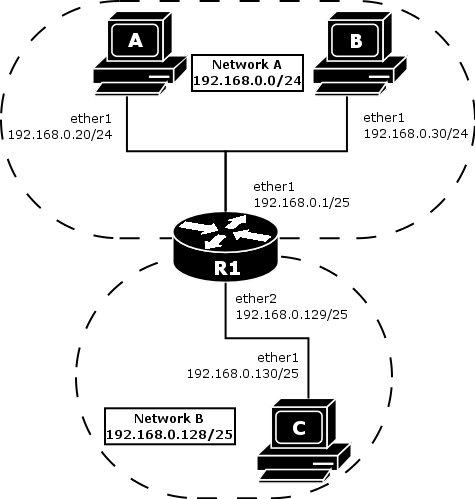
A router with properly configured proxy ARP feature acts like a transparent ARP proxy between directly connected networks. Consider the following network diagram:

Proxy ARP Diagram

Suppose the host A needs to communicate to host C. To do this, it needs to know host's C MAC address. As shown on the diagram above, host A has /24 network mask. That makes host A to believe that it is directly connected to the whole 192.168.0.0/24 network. When a computer needs to communicate to another one on a directly connected network, it sends a broadcast ARP request. Therefore host A sends a broadcast ARP request for the host C MAC address.

Broadcast ARP requests are sent to the broadcast MAC address FF:FF:FF:FF:FF:FF. Since the ARP request is a broadcast, it will reach all hosts in the network A, including the router R1, but it will not reach host C, because routers do not forward broadcasts by default. A router with enabled proxy ARP knows that the host C is on another subnet and will reply with its own MAC adress. The router with enabled proxy ARP always answer with its own MAC address if it has a route to the destination.

This behaviour can be usefull, for example, if you want to assign dial-in (ppp, pppoe, pptp) clients IP addresses from the same address space as used on the connected LAN.

Example

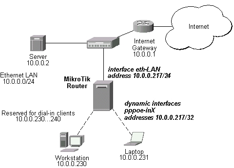
Consider the following configuration:

Proxy-ARP example

The MikroTik Router setup is as follows:

admin@MikroTik] ip arp> /interface ethernet print
Flags: X - disabled, R - running
# NAME MTU MAC-ADDRESS ARP
0 R eth-LAN 1500 00:50:08:00:00:F5 proxy-arp
[admin@MikroTik] ip arp> /interface print
Flags: X - disabled, D - dynamic, R - running
# NAME TYPE MTU
0 eth-LAN ether 1500
1 prism1 prism 1500
2 D pppoe-in25 pppoe-in
3 D pppoe-in26 pppoe-in
[admin@MikroTik] ip arp> /ip address print
Flags: X - disabled, I - invalid, D - dynamic
# ADDRESS NETWORK BROADCAST INTERFACE
0 10.0.0.217/24 10.0.0.0 10.0.0.255 eth-LAN
1 D 10.0.0.217/32 10.0.0.230 0.0.0.0 pppoe-in25
2 D 10.0.0.217/32 10.0.0.231 0.0.0.0 pppoe-in26
[admin@MikroTik] ip arp> /ip route print
Flags: X - disabled, A - active, D - dynamic,
C - connect, S - static, r - rip, b - bgp, o - ospf, m - mme,
B - blackhole, U - unreachable, P - prohibit
# DST-ADDRESS PREF-SRC G GATEWAY DIS INTE...
0 A S 0.0.0.0/0 r 10.0.0.1 1 eth-LAN
1 ADC 10.0.0.0/24 10.0.0.217 0 eth-LAN
2 ADC 10.0.0.230/32 10.0.0.217 0 pppoe-in25
3 ADC 10.0.0.231/32 10.0.0.217 0 pppoe-in26
[admin@MikroTik] ip arp>

Troubleshooting

Description

  • Router shows that the IP address is invalid

    Check whether the interface, the address is assigned to, is present, enabled and running.

Wireless Network technology

Introduction to Wireless

Handheld wireless radios such as this Maritime VHF radio transceiverHandheld wireless radios such as this Maritime VHF radio transceiver use electromagnetic waves to implement a form of wireless communications technology. use electromagnetic waves to implement a form of wireless communications technology.

Wireless operations permits services, such as long range communications, that are impossible or impractical to implement with the use of wires. The term is commonly used in the telecommunications industry to refer to telecommunications systems (e.g., radio transmitters and receivers, remote controls, computer networks, network terminals, etc.) which use some form of energy (e.g. radio frequency (RF), infrared light, laser light, visible light, acoustic energy, etc.) to transfer information without the use of wires.[2] Information is transferred in this manner over both short and long distances.

Wireless communication

The term "wireless" has become a generic and all-encompassing word used to describe communications in which electromagnetic waves or RF (rather than some form of wire) carry a signal over part or the entire communication path. Common examples of wireless equipment in use today include:

  • Professional LMR (Land Mobile Radio) and SMR (Specialized Mobile Radio) typically used by business, industrial and Public Safety entities
  • Consumer Two Way Radio including FRS (Family Radio Service), GMRS (General Mobile Radio Service) and Citizens band ("CB") radios
  • The Amateur Radio Service (Ham radio)
  • Consumer and professional Marine VHF radios
  • Cellular telphones and pagers: provide connectivity for portable and mobile applications, both personal and business.
  • Global Positioning System (GPS): allows drivers of cars and trucks, captains of boats and ships, and pilots of aircraft to ascertain their location anywhere on earth.
  • Cordless computer peripherals: the cordless mouse is a common example; keyboards and printers can also be linked to a computer via wireless.
  • Cordless telephone sets: these are limited-range devices, not to be confused with cell phones.
  • Satellite television: allows viewers in almost any location to select from hundreds of channels.

Wireless networking (i.e. the various flavors of unlicensed 2.4 GHz WiFi devices) is used to meet a variety of needs. Perhaps the most common use is to connect laptop users who travel from location to location. Another common use is for mobile networks that connect via satellite. A wireless transmission method is a logical choice to network a LAN segment that must frequently change locations. The following situations justify the use of wireless technology:

  • To span a distance beyond the capabilities of typical cabling,
  • To avoid obstacles such as physical structures, EMI, or RFI,
  • To provide a backup communications link in case of normal network failure,
  • To link portable or temporary workstations,
  • To overcome situations where normal cabling is difficult or financially impractical, or
  • To remotely connect mobile users or networks.


Wireless communication may be via:

  • radio frequency communication,
  • microwave communication, for example long-range line-of-sight via highly directional antennas, or short-range communication, or
  • infrared (IR) short-range communication, for example from remote controls or via IRDA,

Applications may involve point-to-point communication, point-to-multipoint communication, broadcasting , cellular networks and other wireless networks.

The term "wireless" should not be confused with the term "cordless", which is generally used to refer to powered electrical or electronic devices that are able to operate from a portable power source (e.g., a battery pack) without any cable or cord to limit the mobility of the cordless device through a connection to the mains power supply. Some cordless devices, such as cordless telephones, are also wireless in the sense that information is transferred from the cordless telephone to the telephone's base unit via some type of wireless communications link. This has caused some disparity in the usage of the term "cordless", for example in Digital Enhanced Cordless Telecommunications.

In the last 50 years, wireless communications industry experienced drastic changes driven by many technology innovations.

History

Further information: History of radio

The term "Wireless" came into public use to refer to a radio receiver or transceiver (a dual purpose receiver and transmitter device), establishing its usage in the field of wireless telegraphy early on; now the term is used to describe modern wireless connections such as in cellular networks and wireless broadband Internet. It is also used in a general sense to refer to any type of operation that is implemented without the use of wires, such as "wireless remote control", "wireless energy transfer", etc. regardless of the specific technology (e.g., radio, infrared, ultrasonic, etc.) that is used to accomplish the operation.

Early wireless work

David E. Hughes, eight years before Hertz's experiments, induced electromagnetic waves in a signaling system. Hughes transmitted Morse code by an induction apparatus. In 1878, Hughes's induction transmission method utilized a "clockwork transmitter" to transmit signals. In 1885, T. A. Edison uses a vibrator magnet for induction transmission. In 1888, Edison deploys a system of signaling on the Lehigh Valley Railroad. In 1891, Edison attains the wireless patent for this method using inductance (U.S. Patent 465,971 ).

In the history of wireless technology, the demonstration of the theory of electromagnetic waves by Heinrich Rudolf Hertz in 1888 was important.[3][4] The theory of electromagnetic waves were predicted from the research of James Clerk Maxwell and Michael Faraday. Hertz demonstrated that electromagnetic waves could be transmitted and caused to travel through space at straight lines and that they were able to be received by an experimental apparatus.[3][4] The experiments were not followed up by Hertz and the practical applications of the wireless communication and remote control technology would be implemented by Nikola Tesla.


The electromagnetic spectrum

Light, colours, AM and FM radio, and electronic devices make use of the electromagnetic spectrum. In the US the frequencies that are available for use for communication are treated as a public resource and are regulated by the Federal Communications Commission. This determines which frequency ranges can be used for what purpose and by whom. In the absence of such control or alternative arrangements such as a privatized electromagnetic spectrum, chaos might result if, for example, airlines didn't have specific frequencies to work under and an amateur radio operator was interfering with the pilot's ability to land an airplane. Wireless communication spans the spectrum from 9 kHz to 300 GHz. (Also see Spectrum management)

Applications of wireless technology

Security systems

Wireless technology may supplement or replace hard wired implementations in security systems for homes or office buildings

Television remote control

Modern televisions use wireless (generally infrared) remote control units. Now we also use radio waves.


Cellular telephony (phones and modems)

Perhaps the best known example of wireless technology is the cellular telephone and modems. These instruments use radio waves to enable the operator to make phone calls from many locations world-wide. They can be used anywhere that there is a cellular telephone site to house the equipment that is required to transmit and receive the signal that is used to transfer both voice and data to and from these instruments.

Proxy Configuration Settings

Proxy Configuration Settings
If you are unable to access sites outside Cambridge University, follow the instructions below to configure your system and/or applications to use the University proxy server.

Many applications (such as Software Update, iTunes, RealAudio, Quicktime Player) use the system proxy settings rather than having their own. For this reason it's a good idea to establish system proxy settings.

If you are having problems with an application not listed here then please email student.help@trin.cam.ac.uk and we will add it to the list.

Additional information can be found at G63: How to use the University web proxy and cache

Microsoft Windows

Internet Explorer:

  1. Click Tools>Internet Options>Connections>LAN Settings
  2. Turn off Automatically detect settings
  3. Tick Use automatic configuration script and, in the Address box, type http://www.cam.ac.uk/proxyconfig.pac.
  4. Click OK twice to clear the form and then test the setup by visiting this University Cache test page.
If you still have problems with the settings above, try the following:
  1. In the same location, untick the "Use Automatic Configuration Script" and tick the box next to "Use a Proxy Server for your LAN" below it.
  2. In the address field type: wwwcache.cam.ac.uk
  3. In the Port field type: 8080
  4. Click on the "Advanced" button and in the "Exceptions" box on the window that opens, type *.cam.ac.uk
  5. Click "Ok" on all the settings windows to make the changes.

Mozilla Firefox:

  1. Start Firefox and, from the Tools menu, choose Options. Make sure the General tab is selected.
  2. Click on the Connection Settings button, then type http://www.cam.ac.uk/proxyconfig.pac into the "Automatic proxy configuration URL" box.
  3. Close and restart Firefox to apply settings and test the setup by visiting the University Cache test page.

Microsoft Messenger

  1. Start Messenger and choose Options from the Tools menu.
  2. On the Connection tab, tick I use a proxy server, make sure that HTTP Proxy is selected for Type and write wwwcache.cam.ac.uk in the Server box and 8080 in the Port box.
  3. Click OK and sign in.

Lavasoft Ad-Aware:

  1. On the main screen, click Check for updates now and then click the Configure button.
  2. In the Proxy Settings section, click on Use HTTP Proxy and type wwwcache.cam.ac.uk in the Address box and 8080 in the Port box.

RealOne Player:

  1. On the Tools menu, click Preferences.
  2. In the Category pane under Connection, click Proxy.
  3. Under Streaming Settings, click the Change Settings button at the bottom.
  4. Set PNA and RTSP Proxies to No proxy.
  5. Set HTTP Proxy to Use proxy and enter wwwcache.cam.ac.uk in the first box and 8080 in the port box.
  6. Click OK

Apple Macintosh

System OS X

  1. Open the Apple menu, go to System Preferences and click on Network.
  2. Choose Location: Automatic or create a New Location.
  3. Choose Show: Built-in Ethernet.
  4. Click on the Proxies tab.
  5. Put a tick in Web Proxy (HTTP), type wwwcache.cam.ac.uk in the first box and 8080 in the port box.
  6. Put a tick in Secure Web Proxy, type wwwcache.cam.ac.uk in the first box and 8080 in the port box.
  7. In the Bypass proxy settings for these hosts and domains: box, type *cam.ac.uk, *ja.net. Click Apply Now and close the network panel.
  8. You can test your proxy configuration by visiting the University Cache test page.

System OS 9

  1. Open the Apple menu go to Internet control panel and click on the Advanced tab (if this tab is not visible, select User Mode... from the Edit menu and select the Advanced button)
  2. Select the Firewalls option from the scrolling list at the left
  3. Tick the Web Proxy box and enter wwwcache.cam.ac.uk in the first box and 8080 in the port box.
  4. In the Bypass Proxy Servers box enter *.ac.uk (if your system has a public address) or *.cam.ac.uk (if your system has a CUDN-private address)
  5. Close the Internet Control Panel and test your proxy configuration by visiting the University Cache test page..

linux transparent proxy

Y'day I got a chance to play with Squid and iptables. My job was simple : Setup Squid proxy as a transparent server.

Main benefit of setting transparent proxy is you do not have to setup up individual browsers to work with proxies.

My Setup:

i) System: HP dual Xeon CPU system with 8 GB RAM (good for squid).
ii) Eth0: IP:192.168.1.1
iii) Eth1: IP: 192.168.2.1 (192.168.2.0/24 network (around 150 windows XP systems))
iv) OS: Red Hat Enterprise Linux 4.0 (Following instruction should work with Debian and all other Linux distros)

Eth0 connected to internet and eth1 connected to local lan i.e. system act as router.

Server Configuration

  • Step #1 : Squid configuration so that it will act as a transparent proxy
  • Step #2 : Iptables configuration
    • a) Configure system as router
    • b) Forward all http requests to 3128 (DNAT)
  • Step #3: Run scripts and start squid service

First, Squid server installed (use up2date squid) and configured by adding following directives to file:
# vi /etc/squid/squid.conf

Modify or add following squid directives:
httpd_accel_host virtual
httpd_accel_port 80
httpd_accel_with_proxy on
httpd_accel_uses_host_header on
acl lan src 192.168.1.1 192.168.2.0/24
http_access allow localhost
http_access allow lan

Where,

  • httpd_accel_host virtual: Squid as an httpd accelerator
  • httpd_accel_port 80: 80 is port you want to act as a proxy
  • httpd_accel_with_proxy on: Squid act as both a local httpd accelerator and as a proxy.
  • httpd_accel_uses_host_header on: Header is turned on which is the hostname from the URL.
  • acl lan src 192.168.1.1 192.168.2.0/24: Access control list, only allow LAN computers to use squid
  • http_access allow localhost: Squid access to LAN and localhost ACL only
  • http_access allow lan: -- same as above --

Here is the complete listing of squid.conf for your reference (grep will remove all comments and sed will remove all empty lines, thanks to David Klein for quick hint ):
# grep -v "^#" /etc/squid/squid.conf | sed -e '/^$/d'

OR, try out sed (thanks to kotnik for small sed trick)
# cat /etc/squid/squid.conf | sed '/ *#/d; /^ *$/d'

Output:
hierarchy_stoplist cgi-bin ?
acl QUERY urlpath_regex cgi-bin \?
no_cache deny QUERY
hosts_file /etc/hosts
refresh_pattern ^ftp: 1440 20% 10080
refresh_pattern ^gopher: 1440 0% 1440
refresh_pattern . 0 20% 4320
acl all src 0.0.0.0/0.0.0.0
acl manager proto cache_object
acl localhost src 127.0.0.1/255.255.255.255
acl to_localhost dst 127.0.0.0/8
acl purge method PURGE
acl CONNECT method CONNECT
cache_mem 1024 MB
http_access allow manager localhost
http_access deny manager
http_access allow purge localhost
http_access deny purge
http_access deny !Safe_ports
http_access deny CONNECT !SSL_ports
acl lan src 192.168.1.1 192.168.2.0/24
http_access allow localhost
http_access allow lan
http_access deny all
http_reply_access allow all
icp_access allow all
visible_hostname myclient.hostname.com
httpd_accel_host virtual
httpd_accel_port 80
httpd_accel_with_proxy on
httpd_accel_uses_host_header on
coredump_dir /var/spool/squid

Iptables configuration

Next, I had added following rules to forward all http requests (coming to port 80) to the Squid server port 3128 :
iptables -t nat -A PREROUTING -i eth1 -p tcp --dport 80 -j DNAT --to 192.168.1.1:3128
iptables -t nat -A PREROUTING -i eth0 -p tcp --dport 80 -j REDIRECT --to-port 3128

Here is complete shell script. Script first configure Linux system as router and forwards all http request to port 3128 (Download the fw.proxy shell script):
#!/bin/sh
# squid server IP
SQUID_SERVER="192.168.1.1"
# Interface connected to Internet
INTERNET="eth0"
# Interface connected to LAN
LAN_IN="eth1"
# Squid port
SQUID_PORT="3128"
# DO NOT MODIFY BELOW
# Clean old firewall
iptables -F
iptables -X
iptables -t nat -F
iptables -t nat -X
iptables -t mangle -F
iptables -t mangle -X
# Load IPTABLES modules for NAT and IP conntrack support
modprobe ip_conntrack
modprobe ip_conntrack_ftp
# For win xp ftp client
#modprobe ip_nat_ftp
echo 1 > /proc/sys/net/ipv4/ip_forward
# Setting default filter policy
iptables -P INPUT DROP
iptables -P OUTPUT ACCEPT
# Unlimited access to loop back
iptables -A INPUT -i lo -j ACCEPT
iptables -A OUTPUT -o lo -j ACCEPT
# Allow UDP, DNS and Passive FTP
iptables -A INPUT -i $INTERNET -m state --state ESTABLISHED,RELATED -j ACCEPT
# set this system as a router for Rest of LAN
iptables --table nat --append POSTROUTING --out-interface $INTERNET -j MASQUERADE
iptables --append FORWARD --in-interface $LAN_IN -j ACCEPT
# unlimited access to LAN
iptables -A INPUT -i $LAN_IN -j ACCEPT
iptables -A OUTPUT -o $LAN_IN -j ACCEPT
# DNAT port 80 request comming from LAN systems to squid 3128 ($SQUID_PORT) aka transparent proxy
iptables -t nat -A PREROUTING -i $LAN_IN -p tcp --dport 80 -j DNAT --to $SQUID_SERVER:$SQUID_PORT
# if it is same system
iptables -t nat -A PREROUTING -i $INTERNET -p tcp --dport 80 -j REDIRECT --to-port $SQUID_PORT
# DROP everything and Log it
iptables -A INPUT -j LOG
iptables -A INPUT -j DROP

Save shell script. Execute script so that system will act as a router and forward the ports:
# chmod +x /etc/fw.proxy
# /etc/fw.proxy
# service iptables save
# chkconfig iptables on

Start or Restart the squid:
# /etc/init.d/squid restart
# chkconfig squid on

Desktop / Client computer configuration

Point all desktop clients to your eth1 IP address (192.168.2.1) as Router/Gateway (use DHCP to distribute this information). You do not have to setup up individual browsers to work with proxies.

How do I test my squid proxy is working correctly?

See access log file /var/log/squid/access.log:
# tail -f /var/log/squid/access.log

Above command will monitor all incoming request and log them to /var/log/squid/access_log file. Now if somebody accessing a website through browser, squid will log information.

Problems and solutions

(a) Windows XP FTP Client

All Desktop client FTP session request ended with an error:
Illegal PORT command.

I had loaded the ip_nat_ftp kernel module. Just type the following command press Enter and voila!
# modprobe ip_nat_ftp

Please note that modprobe command is already added to a shell script (above).

(b) Port 443 redirection

I had block out all connection request from our router settings except for our proxy (192.168.1.1) server. So all ports including 443 (https/ssl) request denied. You cannot redirect port 443, from debian mailing list, "Long answer: SSL is specifically designed to prevent "man in the middle" attacks, and setting up squid in such a way would be the same as such a "man in the middle" attack. You might be able to successfully achive this, but not without breaking the encryption and certification that is the point behind SSL".

Therefore, I had quickly reopen port 443 (router firewall) for all my LAN computers and problem was solved.

(c) Squid Proxy authentication in a transparent mode

You cannot use Squid authentication with a transparently intercepting proxy

What Does NAT Do?

What Does NAT Do?

NAT is like the receptionist in a large office. Let's say you have left instructions with the receptionist not to forward any calls to you unless you request it. Later on, you call a potential client and leave a message for that client to call you back. You tell the receptionist that you are expecting a call from this client and to put her through.

The client calls the main number to your office, which is the only number the client knows. When the client tells the receptionist that she is looking for you, the receptionist checks a lookup table that matches your name with your extension. The receptionist knows that you requested this call, and therefore forwards the caller to your extension.

Developed by Cisco, Network Address Translation is used by a device (firewall, router or computer) that sits between an internal network and the rest of the world. NAT has many forms and can work in several ways:

  • Static NAT - Mapping an unregistered IP address to a registered IP address on a one-to-one basis. Particularly useful when a device needs to be accessible from outside the network.


In static NAT, the computer with the IP address of 192.168.32.10 will always translate to 213.18.123.110.

  • Dynamic NAT - Maps an unregistered IP address to a registered IP address from a group of registered IP addresses.


In dynamic NAT, the computer with the IP address 192.168.32.10 will translate to the first available address in the range from 213.18.123.100 to 213.18.123.150.

  • Overloading - A form of dynamic NAT that maps multiple unregistered IP addresses to a single registered IP address by using different ports. This is known also as PAT (Port Address Translation), single address NAT or port-level multiplexed NAT.


In overloading, each computer on the private network is translated to the same IP address (213.18.123.100), but with a different port number assignment.

  • Overlapping - When the IP addresses used on your internal network are registered IP addresses in use on another network, the router must maintain a lookup table of these addresses so that it can intercept them and replace them with registered unique IP addresses. It is important to note that the NAT router must translate the "internal" addresses to registered unique addresses as well as translate the "external" registered addresses to addresses that are unique to the private network. This can be done either through static NAT or by using DNS and implementing dynamic NAT.


The internal IP range (237.16.32.xx) is also a registered range used by another network. Therefore, the router is translating the addresses to avoid a potential conflict with another network. It will also translate the registered global IP addresses back to the unregistered local IP addresses when information is sent to the internal network.

The internal network is usually a LAN (Local Area Network), commonly referred to as the stub domain. A stub domain is a LAN that uses IP addresses internally. Most of the network traffic in a stub domain is local, so it doesn't travel outside the internal network. A stub domain can include both registered and unregistered IP addresses. Of course, any computers that use unregistered IP addresses must use Network Address Translation to communicate with the rest of the world.

NAT, concept of network

Overview

NAT first became popular as a way to deal with the IPv4 address shortage and to avoid all the difficulty of reserving IP addresses. NAT has proven particularly popular in countries other than the United States, which (for historical reasons) have fewer address-blocks allocated per capita. It has become a standard feature in routers for home and small-office Internet connections, where the price of extra IP addresses would often outweigh the benefits. NAT also adds to security as it disguises the internal network's structure: all traffic appears to outside parties as if it originates from the gateway machine.

In a typical configuration, a local network uses one of the designated "private" IP address subnets (the RFC 1918 Private Network Addresses are 192.168.x.x, 172.16.x.x through 172.31.x.x, and 10.x.x.x - using CIDR notation, 192.168/16, 172.16/12, and 10/8), and a router on that network has a private address (such as 192.168.0.1) in that address space. The router is also connected to the Internet with a single "public" address (known as "overloaded" NAT) or multiple "public" addresses assigned by an ISP. As traffic passes from the local network to the Internet, the source address in each packet is translated on the fly from the private addresses to the public address(es). The router tracks basic data about each active connection (particularly the destination address and port). When a reply returns to the router, it uses the connection tracking data it stored during the outbound phase to determine where on the internal network to forward the reply; the TCP or UDP client port numbers are used to demultiplex the packets in the case of overloaded NAT, or IP address and port number when multiple public addresses are available, on packet return. To a system on the Internet, the router itself appears to be the source/destination for this traffic.

It has been argued that the wide adoption of IPv6 would make NAT unnecessary, as NAT is a method of handling the shortage of IPv4 address space.

Drawbacks

Hosts behind NAT-enabled routers do not have true end-to-end connectivity and cannot participate in some Internet protocols. Services that require the initiation of TCP connections from the outside network, or stateless protocols such as those using UDP, can be disrupted. Unless the NAT router makes a specific effort to support such protocols, incoming packets cannot reach their destination. Some protocols can accommodate one instance of NAT between participating hosts ("passive mode" FTP, for example), sometimes with the assistance of an Application Layer Gateway (see below), but fail when both systems are separated from the Internet by NAT. Use of NAT also complicates tunneling protocols such as IPsec because NAT modifies values in the headers which interfere with the integrity checks done by IPsec and other tunneling protocols.

End-to-end connectivity has been a core principle of the Internet, supported for example by the Internet Architecture Board. Current Internet architectural documents observe that NAT is a violation of the End-to-End Principle, but that NAT does have a valid role in careful design.[1] There is considerably more concern with the use of IPv6 NAT, and many IPv6 architects believe IPv6 was intended to remove the need for NAT.[2]

Some Internet service providers (ISPs) only provide their customers with "local" IP addresses.[citation needed]Thus, these customers must access services external to the ISP's network through NAT. As a result, it may be argued[citation needed] that such companies do not properly provide "Internet" service.

Benefits

In addition to the convenience and low cost of NAT, the lack of full bidirectional connectivity can be regarded in some situations as a feature rather than a limitation. To the extent that NAT depends on a machine on the local network to initiate any connection to hosts on the other side of the router, it prevents malicious activity initiated by outside hosts from reaching those local hosts. This can enhance the reliability of local systems by stopping worms and enhance privacy by discouraging scans. Many NAT-enabled firewalls use this as the core of the protection they provide.

The greatest benefit of NAT is that it is a practical solution to the impending exhaustion of IPv4 address space. Networks that previously required a Class B IP range or a block of Class C network addresses can now be connected to the Internet with as little as a single IP address (many home networks are set up this way). The more common arrangement is having machines that require true bidirectional and unfettered connectivity supplied with a 'real' IP address, while having machines that do not provide services to outside users tucked away behind NAT with only a few IP addresses used to enable Internet access.

Basic NAT and PAT

Two kinds of network address translation exist:

  • PAT (Port Address Translation) - The type popularly, but incorrectly, called simply "NAT" (also sometimes named "Network Address Port Translation, NAPT") refers to network address translation involving the mapping of port numbers, allowing multiple machines to share a single IP address.
  • Basic NAT - The other, technically simpler, forms—"one-to-one NAT", "basic NAT", "static NAT" and "pooled NAT"—involve only address translation, not port mapping. This requires an external IP address for each simultaneous connection. Broadband routers often use this feature, sometimes labelled "DMZ host", to allow a designated computer to accept all external connections even when the router itself uses the only available external IP address.

NAT with port-translation (i.e. PAT) comes in two sub-types: source address translation (source NAT), which re-writes the IP address of the computer which initiated the connection; and its counterpart, destination address translation (destination NAT). In practice, both are usually used together in coordination for two-way communication.

NOTE: 'PAT' as it is referred to here is referred to by Cisco as NAT 'overloading' as described in this Howstuffworks article provided to Howstuffworks by Cisco: http://computer.howstuffworks.com/nat3.htm

Relationship between NAT and PAT

PAT is closely related to NAT.

In NAT, generally only the IP addresses are modified: There is a 1:1 correspondence between publicly exposed IP addresses and privately held IP addresses. In PAT, both the sender's private IP and port number are modified; the PAT device chooses the port numbers that will be seen by hosts on the public network.

In NAT, incoming packets are routed to their destination IP address on the private network by reference to the incoming source IP address given by the host on the public network. In PAT, there is generally only one publicly exposed IP address and incoming packets from the public network are routed to their destinations on the private network by reference to a table held within the PAT device that keeps track of public and private port pairs. This is often called connection tracking.

Some devices that claim to offer NAT, such as broadband routers, actually offer PAT. For this reason, there is considerable confusion between the terms. The common use of NAT to include PAT devices suggests that PAT should be considered a type of NAT rather than a distinct technology.

NAT and TCP/UDP

"Pure NAT", operating on IP alone, may or may not correctly pass protocols that are totally concerned with IP information, such as ICMP, depending on whether the payload is interpreted by a host on the "inside" or "outside" of translation. As soon as the protocol stack is climbed, even with such basic protocols such TCP and UDP, the protocols will break unless NAT takes action beyond the network layer.

IP has a checksum in each packet header, which provides error detection only for the header. IP datagrams may become fragmented and it is necessary for a NAT to reassemble these fragments to allow correct recalculation of higher level checksums and correct tracking of which packets belong to which connection.

The major transport layer protocols, TCP and UDP, have a checksum that covers all the data they carry, as well as the TCP/UDP header, plus a "pseudo-header" that contains the source and destination IP addresses of the packet carrying the TCP/UDP header. For an originating NAT to successfully pass TCP or UDP, it must recompute the TCP/UDP header checksum based on the translated IP addresses, not the original ones, and put that checksum into the TCP/UDP header of the first packet of the fragmented set of packets. The receiving NAT must recompute the IP checksum on every packet it passes to the destination host, and also recognize and recompute the TCP/UDP header using the retranslated addresses and pseudo-header. This is not a completely solved problem. One solution is for the receiving NAT to reassemble the entire segment and then recompute a checksum calculated across all packets.

It may be wise for the originating host to do MTU Path Discovery (RFC1191) to determine what MTU will go to the end without fragmentation, and then set the "don't fragment" bit in the appropriate packets. There is no totally general solution to this problem, which is why one of the goals of IPv6 is to avoid NAT.

Applications affected by NAT

Some higher-layer protocols (such as FTP and SIP) send network layer address information inside application payloads. FTP in active mode, for example, uses separate connections for control traffic (commands) and for data traffic (file contents). When requesting a file transfer, the host making the request identifies the corresponding data connection by its network layer and transport layer addresses. If the host making the request lies behind a simple NAT firewall, the translation of the IP address and/or TCP port number makes the information received by the server invalid.

An Application Layer Gateway (ALG) can fix this problem. An ALG software module running on a NAT firewall device updates any payload data made invalid by address translation. ALGs obviously need to understand the higher-layer protocol that they need to fix, and so each protocol with this problem requires a separate ALG.

Another possible solution to this problem is to use NAT traversal techniques using protocols such as STUN or ICE or proprietary approaches in a session border controller. NAT traversal is possible in both TCP- and UDP-based applications, but the UDP-based technique is simpler, more widely understood, and more compatible with legacy NATs. In either case, the high level protocol must be designed with NAT traversal in mind, and it does not work reliably across symmetric NATs or other poorly-behaved legacy NATs.

Other possibilities are UPnP (Universal Plug and Play) or Bonjour (NAT-PMP), but these require the cooperation of the NAT device.

Most traditional client-server protocols (FTP being the main exception), however, do not send layer 3 contact information and therefore do not require any special treatment by NATs. In fact, avoiding NAT complications is practically a requirement when designing new higher-layer protocols today.

NATs can also cause problems where IPsec encryption is applied and in cases where multiple devices such as SIP phones are located behind a NAT. Phones which encrypt their signalling with IPsec encapsulate the port information within the IPsec packet meaning that NA(P)T devices cannot access and translate the port. In these cases the NA(P)T devices revert to simple NAT operation. This means that all traffic returning to the NAT will be mapped onto one client causing the service to fail. There are a couple of solutions to this problem, one is to use TLS which operates at level 4 in the OSI Reference Model and therefore does not mask the port number, or to Encapsulate the IPsec within UDP - the latter being the solution chosen by TISPAN to achieve secure NAT traversal.

It is also a problem with Xbox Live gameplay when the need for players to communicate becomes harder and slows down gameplay.

Different types of NAT

Applications that deal with NAT sometimes need to characterize NAT by type. The STUN protocol proposed to characterize Network address translation as Full cone NAT, restricted cone NAT, port restricted cone NAT or symmetric NAT.[3][4]

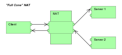
Full cone NAT, also known as one-to-one NAT
  • Once an internal address (iAddr:port1) is mapped to an external address (eAddr:port2), any packets from iAddr:port1 will be sent through eAddr:port2. Any external host can send packets to iAddr:port1 by sending packets to eAddr:port2.
Restricted cone NAT
  • Once an internal address (iAddr:port1) is mapped to an external address (eAddr:port2), any packets from iAddr:port1 will be sent through eAddr:port2. An external host (hostAddr:any) can send packets to iAddr:port1 by sending packets to eAddr:port2 only if iAddr:port1 had previously sent a packet to hostAddr:any. "any" means the port number doesn't matter.
Port restricted cone NAT

Like a restricted cone NAT, but the restriction includes port numbers.

  • Once an internal address (iAddr:port1) is mapped to an external address (eAddr:port2), any packets from iAddr:port1 will be sent through eAddr:port2. An external host (hostAddr:port3) can send packets to iAddr:port1 by sending packets to eAddr:port2 only if iAddr:port1 had previously sent a packet to hostAddr:port3.
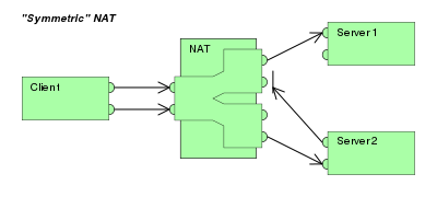
Symmetric NAT
  • Each request from the same internal IP address and port to a specific destination IP address and port is mapped to a unique external source IP address and port.
    If the same internal host sends a packet even with the same source address and port but to a different destination, a different mapping is used.
  • Only an external host that receives a packet from an internal host can send a packet back.

This terminology has been the source of much confusion, as it has proven inadequate at describing real-life NAT behavior.[5] Many NAT implementations combine the specified types, and it is therefore better to refer to specific individual NAT behaviors instead of using the Cone/Symmetric terminology. Especially, most NAT translators combine symmetric NAT for outgoing connections with a static port mapping capability. The latter means that all incoming packets to the specific external address and port can be redirected to a specific internal address and port. Some products can redirect packets to several internal hosts - e.g. to divide the load between a few servers (however, this introduces problems with more sophisticated communications having many interconnected packets and thus is rarely used.

Many NAT implementations follow a port preservation design. For most communications, they will use the same values as internal and external port numbers. However, if two internal hosts attempt to communicate with the same external host using the same port number, the external port number used by the second host will be chosen at random. Such NAT will be sometimes perceived as restricted cone NAT and other times as symmetric NAT.

souce : http://en.wikipedia.org/wiki/Network_address_translation#NAT_and_TCP.2FUDP

Concept TCP/IP Network

Introduction to TCP/IP

Summary: TCP and IP were developed by a Department of Defense (DOD) research project to connect a number different networks designed by different vendors into a network of networks (the "Internet"). It was initially successful because it delivered a few basic services that everyone needs (file transfer, electronic mail, remote logon) across a very large number of client and server systems. Several computers in a small department can use TCP/IP (along with other protocols) on a single LAN. The IP component provides routing from the department to the enterprise network, then to regional networks, and finally to the global Internet. On the battlefield a communications network will sustain damage, so the DOD designed TCP/IP to be robust and automatically recover from any node or phone line failure. This design allows the construction of very large networks with less central management. However, because of the automatic recovery, network problems can go undiagnosed and uncorrected for long periods of time.

As with all other communications protocol, TCP/IP is composed of layers:

  • IP - is responsible for moving packet of data from node to node. IP forwards each packet based on a four byte destination address (the IP number). The Internet authorities assign ranges of numbers to different organizations. The organizations assign groups of their numbers to departments. IP operates on gateway machines that move data from department to organization to region and then around the world.
  • TCP - is responsible for verifying the correct delivery of data from client to server. Data can be lost in the intermediate network. TCP adds support to detect errors or lost data and to trigger retransmission until the data is correctly and completely received.
  • Sockets - is a name given to the package of subroutines that provide access to TCP/IP on most systems.

Network of Lowest Bidders

The Army puts out a bid on a computer and DEC wins the bid. The Air Force puts out a bid and IBM wins. The Navy bid is won by Unisys. Then the President decides to invade Grenada and the armed forces discover that their computers cannot talk to each other. The DOD must build a "network" out of systems each of which, by law, was delivered by the lowest bidder on a single contract.

ipdept.gif

The Internet Protocol was developed to create a Network of Networks (the "Internet"). Individual machines are first connected to a LAN (Ethernet or Token Ring). TCP/IP shares the LAN with other uses (a Novell file server, Windows for Workgroups peer systems). One device provides the TCP/IP connection between the LAN and the rest of the world.

To insure that all types of systems from all vendors can communicate, TCP/IP is absolutely standardized on the LAN. However, larger networks based on long distances and phone lines are more volatile. In the US, many large corporations would wish to reuse large internal networks based on IBM's SNA. In Europe, the national phone companies traditionally standardize on X.25. However, the sudden explosion of high speed microprocessors, fiber optics, and digital phone systems has created a burst of new options: ISDN, frame relay, FDDI, Asynchronous Transfer Mode (ATM). New technologies arise and become obsolete within a few years. With cable TV and phone companies competing to build the National Information Superhighway, no single standard can govern citywide, nationwide, or worldwide communications.

The original design of TCP/IP as a Network of Networks fits nicely within the current technological uncertainty. TCP/IP data can be sent across a LAN, or it can be carried within an internal corporate SNA network, or it can piggyback on the cable TV service. Furthermore, machines connected to any of these networks can communicate to any other network through gateways supplied by the network vendor.

Addresses

Each technology has its own convention for transmitting messages between two machines within the same network. On a LAN, messages are sent between machines by supplying the six byte unique identifier (the "MAC" address). In an SNA network, every machine has Logical Units with their own network address. DECNET, Appletalk, and Novell IPX all have a scheme for assigning numbers to each local network and to each workstation attached to the network.

On top of these local or vendor specific network addresses, TCP/IP assigns a unique number to every workstation in the world. This "IP number" is a four byte value that, by convention, is expressed by converting each byte into a decimal number (0 to 255) and separating the bytes with a period. For example, the PC Lube and Tune server is 130.132.59.234.

An organization begins by sending electronic mail to Hostmaster@INTERNIC.NET requesting assignment of a network number. It is still possible for almost anyone to get assignment of a number for a small "Class C" network in which the first three bytes identify the network and the last byte identifies the individual computer. The author followed this procedure and was assigned the numbers 192.35.91.* for a network of computers at his house. Larger organizations can get a "Class B" network where the first two bytes identify the network and the last two bytes identify each of up to 64 thousand individual workstations. Yale's Class B network is 130.132, so all computers with IP address 130.132.*.* are connected through Yale.

The organization then connects to the Internet through one of a dozen regional or specialized network suppliers. The network vendor is given the subscriber network number and adds it to the routing configuration in its own machines and those of the other major network suppliers.

There is no mathematical formula that translates the numbers 192.35.91 or 130.132 into "Yale University" or "New Haven, CT." The machines that manage large regional networks or the central Internet routers managed by the National Science Foundation can only locate these networks by looking each network number up in a table. There are potentially thousands of Class B networks, and millions of Class C networks, but computer memory costs are low, so the tables are reasonable. Customers that connect to the Internet, even customers as large as IBM, do not need to maintain any information on other networks. They send all external data to the regional carrier to which they subscribe, and the regional carrier maintains the tables and does the appropriate routing.

New Haven is in a border state, split 50-50 between the Yankees and the Red Sox. In this spirit, Yale recently switched its connection from the Middle Atlantic regional network to the New England carrier. When the switch occurred, tables in the other regional areas and in the national spine had to be updated, so that traffic for 130.132 was routed through Boston instead of New Jersey. The large network carriers handle the paperwork and can perform such a switch given sufficient notice. During a conversion period, the university was connected to both networks so that messages could arrive through either path.

Subnets

Although the individual subscribers do not need to tabulate network numbers or provide explicit routing, it is convenient for most Class B networks to be internally managed as a much smaller and simpler version of the larger network organizations. It is common to subdivide the two bytes available for internal assignment into a one byte department number and a one byte workstation ID.

classb.gif

The enterprise network is built using commercially available TCP/IP router boxes. Each router has small tables with 255 entries to translate the one byte department number into selection of a destination Ethernet connected to one of the routers. Messages to the PC Lube and Tune server (130.132.59.234) are sent through the national and New England regional networks based on the 130.132 part of the number. Arriving at Yale, the 59 department ID selects an Ethernet connector in the C& IS building. The 234 selects a particular workstation on that LAN. The Yale network must be updated as new Ethernets and departments are added, but it is not effected by changes outside the university or the movement of machines within the department.

A Uncertain Path

Every time a message arrives at an IP router, it makes an individual decision about where to send it next. There is concept of a session with a preselected path for all traffic. Consider a company with facilities in New York, Los Angeles, Chicago and Atlanta. It could build a network from four phone lines forming a loop (NY to Chicago to LA to Atlanta to NY). A message arriving at the NY router could go to LA via either Chicago or Atlanta. The reply could come back the other way.

How does the router make a decision between routes? There is no correct answer. Traffic could be routed by the "clockwise" algorithm (go NY to Atlanta, LA to Chicago). The routers could alternate, sending one message to Atlanta and the next to Chicago. More sophisticated routing measures traffic patterns and sends data through the least busy link.

If one phone line in this network breaks down, traffic can still reach its destination through a roundabout path. After losing the NY to Chicago line, data can be sent NY to Atlanta to LA to Chicago. This provides continued service though with degraded performance. This kind of recovery is the primary design feature of IP. The loss of the line is immediately detected by the routers in NY and Chicago, but somehow this information must be sent to the other nodes. Otherwise, LA could continue to send NY messages through Chicago, where they arrive at a "dead end." Each network adopts some Router Protocol which periodically updates the routing tables throughout the network with information about changes in route status.

If the size of the network grows, then the complexity of the routing updates will increase as will the cost of transmitting them. Building a single network that covers the entire US would be unreasonably complicated. Fortunately, the Internet is designed as a Network of Networks. This means that loops and redundancy are built into each regional carrier. The regional network handles its own problems and reroutes messages internally. Its Router Protocol updates the tables in its own routers, but no routing updates need to propagate from a regional carrier to the NSF spine or to the other regions (unless, of course, a subscriber switches permanently from one region to another).

Undiagnosed Problems

IBM designs its SNA networks to be centrally managed. If any error occurs, it is reported to the network authorities. By design, any error is a problem that should be corrected or repaired. IP networks, however, were designed to be robust. In battlefield conditions, the loss of a node or line is a normal circumstance. Casualties can be sorted out later on, but the network must stay up. So IP networks are robust. They automatically (and silently) reconfigure themselves when something goes wrong. If there is enough redundancy built into the system, then communication is maintained.

In 1975 when SNA was designed, such redundancy would be prohibitively expensive, or it might have been argued that only the Defense Department could afford it. Today, however, simple routers cost no more than a PC. However, the TCP/IP design that, "Errors are normal and can be largely ignored," produces problems of its own.

Data traffic is frequently organized around "hubs," much like airline traffic. One could imagine an IP router in Atlanta routing messages for smaller cities throughout the Southeast. The problem is that data arrives without a reservation. Airline companies experience the problem around major events, like the Super Bowl. Just before the game, everyone wants to fly into the city. After the game, everyone wants to fly out. Imbalance occurs on the network when something new gets advertised. Adam Curry announced the server at "mtv.com" and his regional carrier was swamped with traffic the next day. The problem is that messages come in from the entire world over high speed lines, but they go out to mtv.com over what was then a slow speed phone line.

Occasionally a snow storm cancels flights and airports fill up with stranded passengers. Many go off to hotels in town. When data arrives at a congested router, there is no place to send the overflow. Excess packets are simply discarded. It becomes the responsibility of the sender to retry the data a few seconds later and to persist until it finally gets through. This recovery is provided by the TCP component of the Internet protocol.

TCP was designed to recover from node or line failures where the network propagates routing table changes to all router nodes. Since the update takes some time, TCP is slow to initiate recovery. The TCP algorithms are not tuned to optimally handle packet loss due to traffic congestion. Instead, the traditional Internet response to traffic problems has been to increase the speed of lines and equipment in order to say ahead of growth in demand.

TCP treats the data as a stream of bytes. It logically assigns a sequence number to each byte. The TCP packet has a header that says, in effect, "This packet starts with byte 379642 and contains 200 bytes of data." The receiver can detect missing or incorrectly sequenced packets. TCP acknowledges data that has been received and retransmits data that has been lost. The TCP design means that error recovery is done end-to-end between the Client and Server machine. There is no formal standard for tracking problems in the middle of the network, though each network has adopted some ad hoc tools.

Need to Know

There are three levels of TCP/IP knowledge. Those who administer a regional or national network must design a system of long distance phone lines, dedicated routing devices, and very large configuration files. They must know the IP numbers and physical locations of thousands of subscriber networks. They must also have a formal network monitor strategy to detect problems and respond quickly.

Each large company or university that subscribes to the Internet must have an intermediate level of network organization and expertise. A half dozen routers might be configured to connect several dozen departmental LANs in several buildings. All traffic outside the organization would typically be routed to a single connection to a regional network provider.

However, the end user can install TCP/IP on a personal computer without any knowledge of either the corporate or regional network. Three pieces of information are required:

  1. The IP address assigned to this personal computer
  2. The part of the IP address (the subnet mask) that distinguishes other machines on the same LAN (messages can be sent to them directly) from machines in other departments or elsewhere in the world (which are sent to a router machine)
  3. The IP address of the router machine that connects this LAN to the rest of the world.

In the case of the PCLT server, the IP address is 130.132.59.234. Since the first three bytes designate this department, a "subnet mask" is defined as 255.255.255.0 (255 is the largest byte value and represents the number with all bits turned on). It is a Yale convention (which we recommend to everyone) that the router for each department have station number 1 within the department network. Thus the PCLT router is 130.132.59.1. Thus the PCLT server is configured with the values:

  • My IP address: 130.132.59.234
  • Subnet mask: 255.255.255.0
  • Default router: 130.132.59.1

The subnet mask tells the server that any other machine with an IP address beginning 130.132.59.* is on the same department LAN, so messages are sent to it directly. Any IP address beginning with a different value is accessed indirectly by sending the message through the router at 130.132.59.1 (which is on the departmental LAN).

Additional information is available in self-study courses from SRA (1-800-SRA-1277)